Reverse Polarity Protection
or how I learned to stop worrying and love the magic smoke
(Full Article from the T5W excerpt)
Reverse Polarity Protection kits are available in the store or try your hand at SMD with our RPP-SMD version.
We have all done it, or will one day, hook the power cables to the radio backwards. Hopefully little to nothing will happen. Sometimes it’s a minor repair like replacing a fuse or regulator. But on others you watch the equipment lose all it’s magic smoke. Here are a few simple tips and tricks you can use to help keep that magic smoke from leaving your rig. For measured examples we used a Heathkit HW-8 and a Chinese Super RM Rockmite.
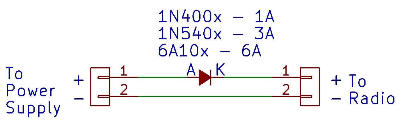
Series Diode – By far the cheapest and easiest to install is a diode in series with the positive power lead. Anode toward the power supply and Cathode (banded end) going to the radio. For a few pennies a 1N400x series diode will handle many QRP rigs up to 1A and a 1N540x series will work up to 3A. Although simple and cheap it comes at a cost. The diode will drop about 0.6-0.9V which could result in lower transmit power and if the equipment uses voltage regulators this lower voltage may be under the regulator level.
Bridge Rectifier – The most foolproof for reverse polarity protection. For about a dollar or two, the bridge will correct the polarity no matter how you connect the power supply. With a bridge there are always 2 diodes conducting which can result in greater losses of round .8-1.5V. This works good only when a single power supply is used with a single radio but should be avoided when multiple pieces of equipment are connected together via the grounds.

Fuse with crowbar diode – With most protection circuits there is usually some form of loss in the process, as seen in the diode examples above. However, the fuse with crowbar diode has no voltage drop loss. The crowbar works by putting a diode across the voltage lines with the Cathode toward the positive side. This in effect leaves the path through the diode open unless the polarity is reversed. When that happens the diode now becomes an almost short circuit causing the fuse to blow. The cost of course if that a hefty diode needs to be used to handle the large current flow until the fuse opens up, not to mention a new fuse each time it’s tested.

MOSFET1 – Not only can MOFSET’s do a great job at switching, a P-channel MOSFET does an excellent job of reverse polarity protection. Depending on your needs the cost is from a few pennies to a dollar or two. Under normal circumstances the MOSFET is turned on with a small voltage drop across it, typically fractions less than the diode example above. When the polarity is reversed the MOSFET is forced off and creates an open circuit. See the sidebar on MOSFET selection for more information in selecting a P-channel MOSFET.

MOSFET RPP Rules:
- VDS – Voltage Drain to Source – must be greater than the power supply voltage.
- RDS(on) – Resistance of the Drain to Source when the MOSFET is turned on. This must be as low as possible. The lower the RDS(on) the less voltage drop and heat for those high current uses. Usually the lower the Rds(on) the more expensive.
- Vgss – Voltage from Gate to Source – The maximum voltage allowed from Gate to Source. This should also be greater than the power supply voltage. Many MOSFET’s will have a lower Vgss. In these cases the addition of a simple zener diode and resistor are required as follows:
- Resistor is not critical, almost any value between 10K and 100K is good.
- Zener voltage must be less than the MOSFET Vgss. Additionally it must be greater than the MOSFET Vgs(th) – Threshold Voltage from Gate to Source – This is the minimum voltage required to fully turn on the MOSFET.
- There is a small capacitor in the Drain to Gate circuitry. This capacitor is optional but recommended and only used for static discharge protection.2

 MOSFET RPP installed in an HW-8
Tests of various RPP devices
Heathkit HW-8
| Receive | Transmit | |||||||||
| Device | V | Vdrop | I-mA | V | Vdrop | I-A | W | Loss-W | Loss-dB | Notes |
| NO RPP | 13.48 | 0.00 | 111.0 | 13.45 | 0.00 | 0.42 | 2.25 | 0.00 | 0.00 | Reference |
| 1N4001 Diode | 12.66 | -0.82 | 95.9 | 12.61 | -0.84 | 0.40 | 2.00 | -0.25 | -0.51 | |
| 1N5401 Diode | 12.65 | -0.83 | 95.4 | 12.59 | -0.86 | 0.40 | 1.95 | -0.30 | -0.62 | |
| KBPC3510 Bridge | 12.70 | -0.78 | 95.4 | 12.52 | -0.93 | 0.40 | 1.90 | -0.35 | -0.73 | |
| NTD2955 MOSFET | 13.46 | -0.02 | 110.0 | 13.37 | -0.08 | 0.42 | 2.20 | -0.10 | -0.10 | .155 Ohms |
| IRF4905 MOSFET | 13.48 | 0.00 | 111.0 | 13.45 | 0.00 | 0.42 | 2.25 | 0.00 | 0.00 | .02 Ohms |
Super RM Rockmite
| Receive | Transmit | |||||||||
| Device | V | Vdrop | I-mA | V | Vdrop | I-A | W | Loss-W | Loss-dB | Notes |
| NO RPP | 13.48 | 0.00 | 66.4 | 13.41 | 0.00 | 1.30 | 5.1 | 0.00 | 0.00 | Reference |
| 1N4001 Diode | 12.83 | -0.65 | 65.4 | 12.58 | -0.83 | 1.26 | 5.0 | -0.10 | -0.09 | not recommended |
| 1N5401 Diode | 12.74 | -0.74 | 65.3 | 12.54 | -0.87 | 1.26 | 5.0 | -0.10 | -0.09 | |
| KBPC2510 Bridge | 12.75 | -0.73 | 65.2 | 12.05 | -1.36 | 1.16 | 5.0 | -0.15 | -0.13 | |
| NTD2955 MOSFET | 13.47 | -0.01 | 66.4 | 12.98 | -0.43 | 1.28 | 5.1 | -0.05 | -0.04 | .155 Ohms |
| IRD4905 MOSFET | 13.48 | 0.00 | 66.4 | 13.37 | -0.04 | 1.30 | 5.1 | 0.00 | 0.00 | .02 Ohms |
Definitions
V – Power Supply Voltage measured at the radio during receive.
VDrop – The voltage drop measured across the RPP device.
I – Current draw.
W – The power in Watts during transmit.
Loss-W – The power difference when the RPP device is installed.
Loss-dB – The power difference converted to dB. Loss = 10 * log(Wtx/Wref).
Notes:
- “NO RPP” is used as a reference.
- The 1N4001 was tested on the Rockmite but not recommended since the diode is rated for 1A and current draw exceeds 1A.
- Rds(on) ratings of the selected MOSFET.
References:
- https://www.infineon.com/dgdl/Reverse-Batery-Protection-Rev2.pdf?fileId=db3a304412b407950112b41887722615
- http://www.arrl.org/files/file/Technology/HandsOnRadio/Thoughts%20on%20Reverse%20Power%20Protection%20using%20Power%20MOSFETs%20-%20Wheeler%20N0GSG.pdf
- https://www.youtube.com/watch?v=IrB-FPcv1Dc
Hi Power Post Testing:
We put an IRF4905 unit to the test on an Icom IC-725 transceiver. No heatsink has been added!
A 6A Load at 30 seconds became warm with a 210mV drop.
A 10A load at 30 seconds became hot with a 380mV drop
Transmit Loss: No RPP: 100W w/ RPP: 98W
1 minute of 10WPM CW Heat testing:
100W MOSFET = too hot to touch (smell the heat!).
50W MOSFET = too hot to touch
20W MOSFET = Warm but not hot
10W MOSFET = Barely Warm
JT65 45 second transmission @ 15W MOSFET = Barely Warm
After 5 JT65 transmission cycles: MOSFET = hot but touchable
You must be logged in to post a comment.